180° and the 360° Adjustable Drip Emitters
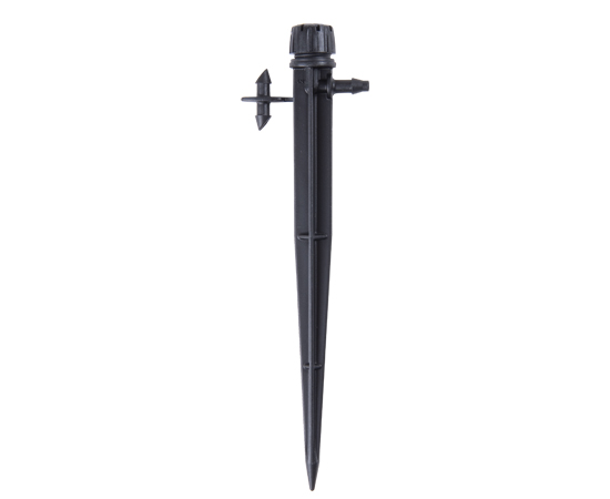
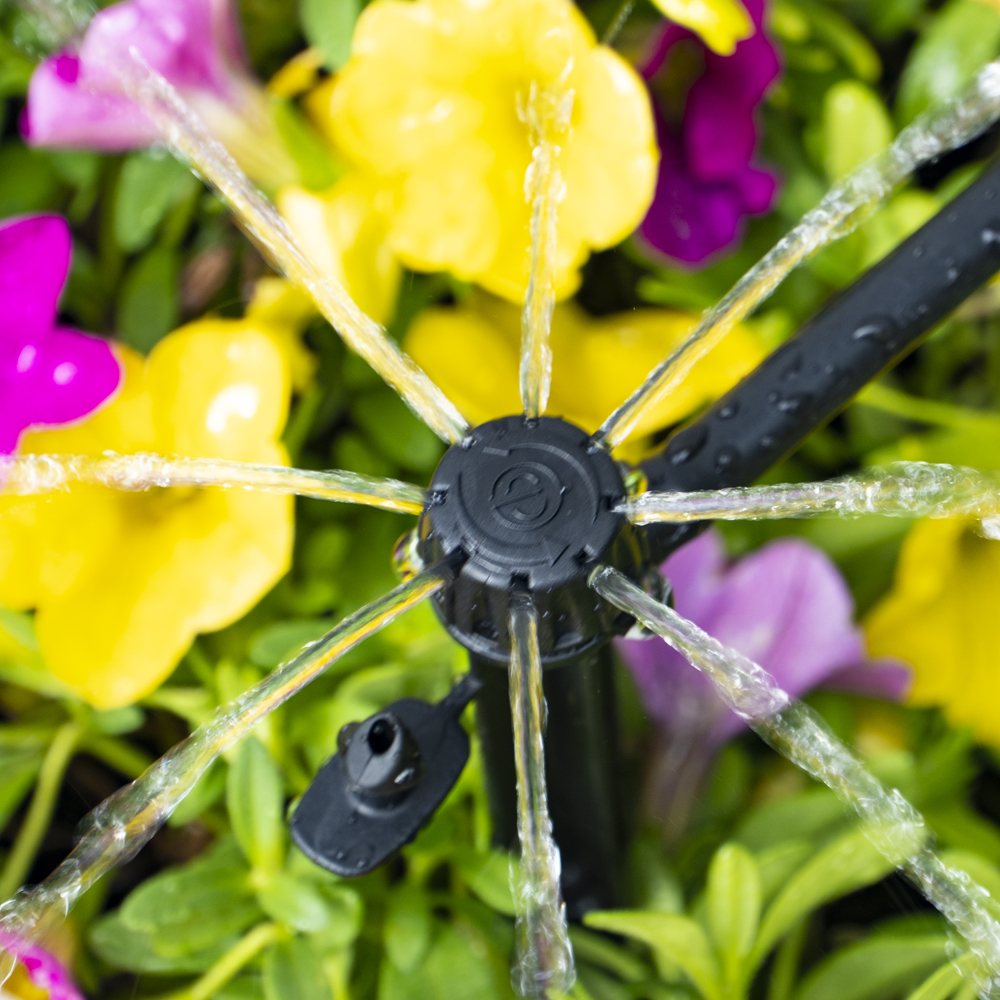
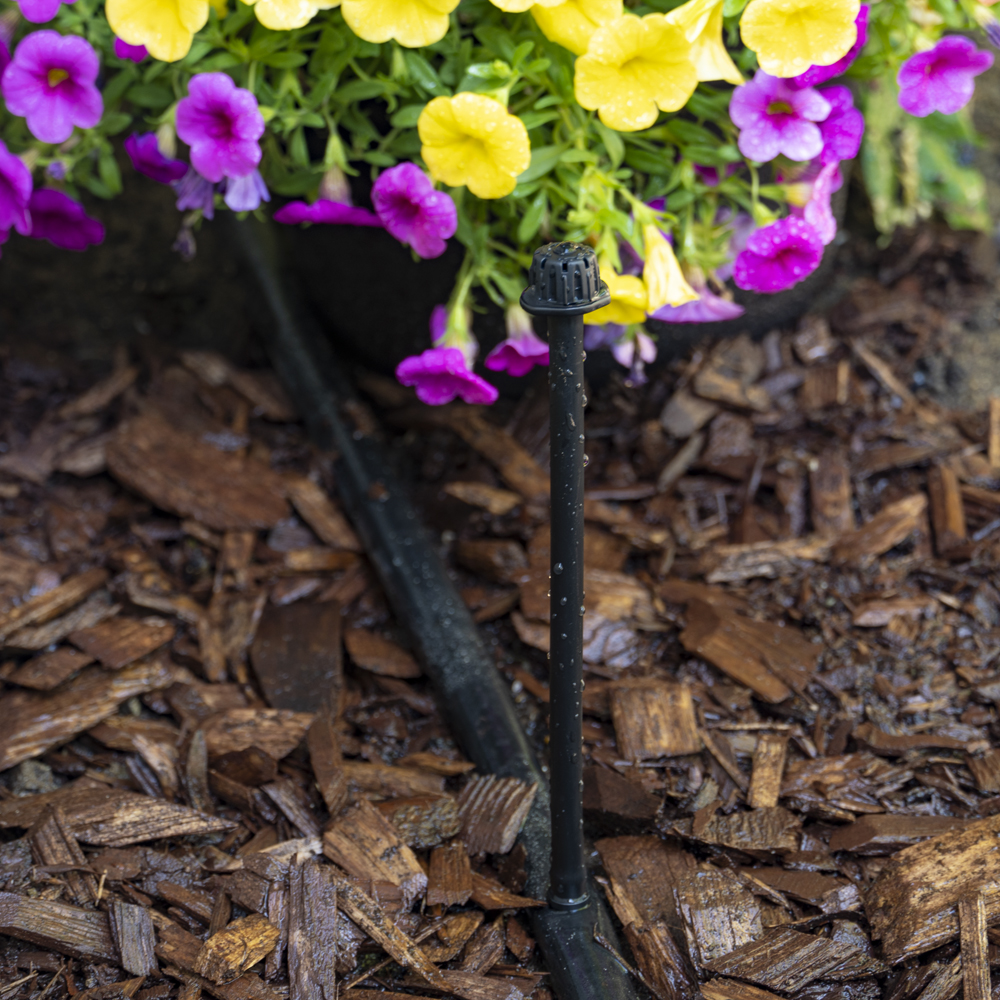
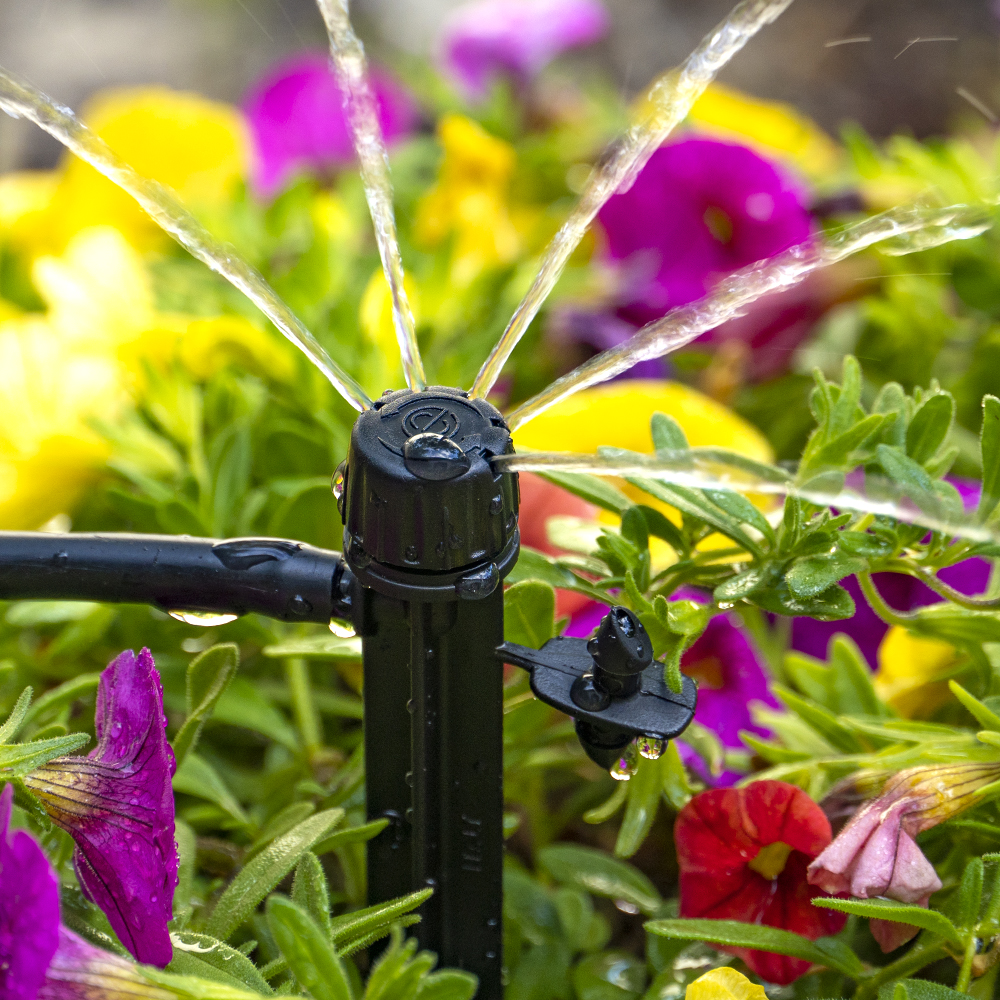
DIG’s Adjustable Stream Drip Emitters are available in a 180° or 360° pattern and with 1/4” barb or 6” spike. The adjustable Stream Drip Emitters are designed to produce a very low flow to gentle stream pattern with an adjustable flow of up to 14.1 GPH and a diameter of up to 2.3’ at 25 PSI. The adjustable stream drip emitters have a rotating cap that allows for simultaneous control of the flow and the wetted area. As your plants grow, they require more water to flourish and the flow and the area covered can be increased to support the plants’ growth. Used for an individual plant, group of plants, planter boxes, small to large pots, groundcovers, shrubs and trees, these adjustable drip emitters offer a convenient way to water areas where conventional sprinkler systems are not practical. Available in a wide range of pack quantities and configurations, including 360° Adjustable Stream Drip Emitters with ¼” barb, models B05B (pack of 5), B10B (pack of 10) and B25B (pack of 25), 360° Adjustable Stream Drip Emitters on Spike, model BA1B (pack of 4), B10B (pack of 10) and BA1PRO (pack of 25), 180° Adjustable Stream Drip Emitters with ¼” barb model B10C (pack of 10) and 180° Adjustable Stream Drip Emitters on Spike, model BA5C (pack of 5).
Features
- Available in 360° and 180° patterns for individual plants or closely spaced plantings
- Recommended for planter boxes, large pots, groundcovers and shrubs
- Rotation of the cap allows adjustment of flow and diameter of throw down to a complete shut-off via a ratchet mechanism on the cap and a notch on the base
- Can be extended with 1/4″ micro tubing or connected into the 1/2″ drip tubing or supply line
- Efficient and reliable method for applying water
- Trouble-free operation with no moving parts
- Drip emitter caps can be removed for easy cleaning
- Includes 1/4 in. extra barbed connector on the spike for securing 1/4 in. micro tubing to 1/2 in. poly tubing
- Low flow with gentle stream pattern
- Removable cap for easy cleaning
- Constructed of UV-resistant, durable plastic material
How to Order
| MODEL | DESCRIPTION | IMAGE |
|---|---|---|
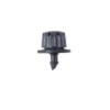
| BT5B | Adjustable Dripper on 10/32 Thread |
|
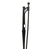
| ASD-1B | Adjustable Stream Drip Emitter Assembly on 13" Clip Stake w/ 12" PE Riser & Barb |
|
| 360° On Barb | ||
| B05B | 360° Adjustable Drippers Emitter On Barb (pack of 5) |
|
| B10B | 360° Adjustable Drippers Emitter On Barb (pack of 10) |
|
| B25B | 360° Adjustable Drippers Emitter On Barb (pack of 25) |
|
| 180° On Barb | ||
| B10C | 180° Adjustable Drippers Emitter On Barb (pack of 10) |
|
| 360° On Spike | ||
| BA1B | 360° Adjustable Drippers Emitter On Spike (pack of 4) |
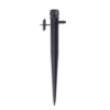
|
| BA10B | 360° Adjustable Drippers Emitter On Spike (pack of 10) |
|
| BA1PRO | 360° Adjustable Drippers Emitter On Spike (pack of 25) |
|
| 180° On Spike | ||
| BA5C | 180° Adjustable Drippers Emitter On Spike (pack of 5) |
|
Specifications
- Pattern: 360° and 180°
- Recommended operating pressure: 25 PSI with flow rate of 14.1 GPH (use with model D46 25-PSI pressure regulator)
- Wetting area: 0 to 2.3’ at 15 to 25 PSI
- Maximum operating pressure range: Up to 30 PSI with flow rate of up to 15.7 GPH
- Maximum flow rate up to 15.7 GPH at 30 PSI with approximately 20 clicks
- Mounting options: ¼” barb or 6” spike
- Filter requirement: minimum of 120 mesh
- Recommended spacing: 2’ to 4’ apart when completely open or one per each plant
- Material:
- Body and stake: polypropylene
Adjustable flow rate, and diameter
| Pressure | Drip | Flow rate | diameter |
|---|---|---|---|
| PSI | drip emitter base | GPH | 360° x 8 stream |
| 15 | Black | 0-11 | 0-1.5' |
| 20 | Black | 0-12.5 | 0-1.9' |
| 25 | Black | 0-14.1 | 0-2.3' |
| 30 | Black | 0-15.7 | 0-2.7' |
Maximum number of adjustable stream drip emitters on 1/2" drip tubing with .600 ID
| Spacing | 2' | 3' | 4' | 5' | 6' |
|---|---|---|---|---|---|
| Flow rate @ 30 PSI | 15.7 | 15.7 | 15.7 | 15.7 | 15.7 |
| Maximum length | 40' | 51 | 65' | 70' | 78' |
| Flow rate in GPM | 5.23 | 4.45 | 4.19 | 3.66 | 3.40 |
| Flow rate in GPH | 314 | 266.9 | 251.2 | 219.8 | 204.1 |
| # of adjustable stream drip emitters | 20 | 17 | 16 | 14 | 13 |
| Head loss in PSI | 5.0 | 4.7 | 5.3 | 4.5 | 4.4 |
| Velocity (f/s) | 5.95 | 5.05 | 4.76 | 4.16 | 3.86 |
| 48" micro tubing head loss in PSI | 0.5 | 0.5 | 0.5 | 0.5 | 0.5 |
| Total head loss at the drip emitter | 5.5 | 5.2 | 5.8 | 5.0 | 4.9 |
Videos
-
DIG Drip Irrigation System Installation: Connecting Adjustable Drippers
About
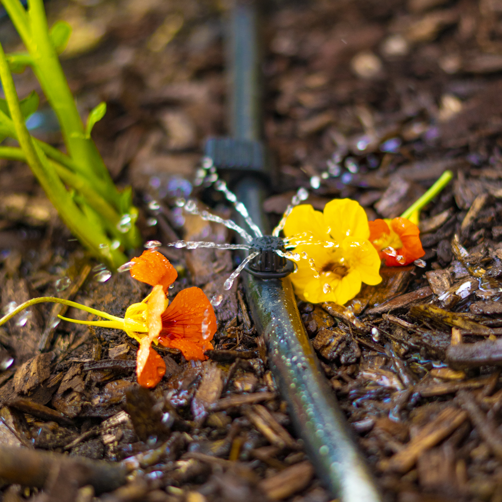
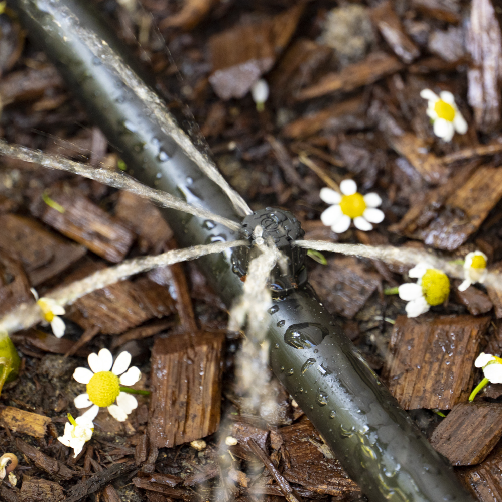
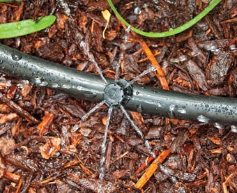
The 180° and the 360° Adjustable Stream Drip Emitters have a flow range from 0 to 14.1 GPH at a recommended preset pressure of 25 PSI. When the cap is rotated, the 180° and the 360° Adjustable Stream Drip Emitters flow and radius of the wetted area change from drip to a gentle stream pattern and then turn off as you rotate to close. This feature allows the user to adjust the flow to each individual plant as needed. Rotating the cap towards the “+” or the “-” signs allows the user to increase or decrease the flow rate. DIG’s 180° and the 360° Adjustable Stream Drip Emitters available with 1/4″ barb and a 6″ spike with a 1/4″ barb inlet and side barb. These Adjustable Stream Drip Emitters are ideal for watering a group of plants or under a large individual plant.
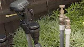
The 180° and the 360° Adjustable Stream Drip Emitters may be installed using one of two methods: either directly into the drip tubing or at the end of the micro tubing with each head placed under the plant canopy, at the center between the plant trunk and the plant canopy edge. The 180° and the 360° Adjustable Stream Drip Emitters on Spike are ideal when extended from the main poly drip tubing, and mounted about five inches above ground for good visibility. The 180° and the 360° Adjustable Stream Drip Emitters with barb can be mounted directly into the poly drip tubing. One of the most common installation errors is using too few drip emitters per plant. All too often only a single emitter is placed at the base of a newly planted tree or shrub. In clay soils, a single drip emitter can wet a three to four foot diameter; on sandy soils, the same layout using the same drip emitter will only wet an area less than one foot in diameter. Given the fact that plant roots can grow up to a few feet a year depending on the plant and location, after one year the diameter of the root area could be much larger than the area covered by the emitter. A single emitter per tree or shrub could restrict root development as early as the first year after planting if flow is not adjusted.
Installation suggestions
Basic installation recommendations for this product include first reviewing the area and then making a drawing of the garden or site with a layout. If automation is required, use one of DIG’s hose end timers or battery operated controllers, model B09D for a battery operated hose end and EVO100 for a solar powered hose end. For a valve box use our RBC7000 battery operated timer with a 3/4″ inline valve, for above the ground use our RBC8000 with 3/4″ anti-siphon valve. The ideal timer or controller should have flexible scheduling and two to four start times per day for added flexibility.
Start the installation from a PVC pipe or to pipe thread
- If the system installation is started from a PVC pipe, first shut off the main water supply.
- If an automated system is preferred, we recommend installing a 3/4” ball valve or gate valve before the battery operated controller or AC valve, if used. This ball valve can be very useful as an emergency backup to turn the system off. This
type of arrangement is used by professional installers. - Turn the water supply on to flush the line and then shut the water supply off using the new ball or gate valve.
- Install an AC valve or battery operated controller, wrapping TEFLON tape on all the male thread fittings used.
- Turn the water supply on again to pressurize the system. The unit will open momentarily and then will shut off.
- Test the valve or the battery operated controller and make sure that it is working correctly.
- After the AC valve or battery operated controller, add a 3/4″ screen filter with 155-mesh (model D55). The screen filter is used to protect the drip system. Then add a preset 25 PSI pressure regulator (model D46P) or adjustable pressure regulator (model PRV075). The pressure regulator is used to lower the pressure to the suggested operating pressure for a drip system. Follow with a 3/4” swivel adapter (model 50001) to the drip tubing or 3/4” PVC thread x slip adapter to the PVC line.
Start the installation from a faucet or hose thread
- If an automated system is preferred, install a hose end timer.
- Test the timer and make sure that it is working correctly.
- To the timer, add a backflow device (model D45), a 25 PSI pressure regulator (model D46) and then a 3/4″ swivel adapter with a screen (model C34). If water quality is a concern, we highly recommend using our fine mesh 3/4″ filter with 155-mesh (model D57A).
Product installation
- Using the poly drip tubing as the main lateral or as a sub lateral, lay out the poly drip tubing per your layout drawing. Secure the poly drip tubing to the ground using stakes (model R60) and add more stakes as you unroll the poly drip tubing. Add stakes every 6′-10’ and at the end of each section or as needed. An extra 1% of poly drip tubing length should be added to each lateral to compensate for contraction at low temperature.
- Throughout the installation and per your drawing layout, add, if needed, 1/2” fittings, such as tees (model C35) and elbows (model C36), leaving the end of the poly drip tubing open. To install the 1/2″ compression drip fittings, cut the poly drip tubing with a hand pruner, being careful to keep dirt from entering the line. Hold the fitting in one hand and the poly drip tubing in the other and force the poly drip tubing into the compression fitting by wiggling it from side to side.
- The 180° and the 360° adjustable drip emitters are installed along the ploy drip tubing at varying or at specific intervals. The distribution uniformity of water from the 180° and the 360° adjustable drip emitters along the line will depends on the incoming pressure, number of adjustable drip emitters used per lateral, and the length of the laterals. Special care should be taken to ensure high uniformity of water along the laterals by not exceeding the product recommendations (see chart below).
- To install the 180° and the 360° adjustable drip emitters with the 1/4″ barbs, punch a hole into the poly drip tubing using the small punch (model D44) or the gun punch (model 16-035), and snap the 180° and the 360° adjustable drip emitters with a 1/4” barb into the poly drip tubing.
To install the 180° and the 360° adjustable drip emitters with spike, cut a length of two to four feet (we highly recommend not exceeding four feet) of 1/4″ micro tubing (vinyl – models B38 for 50’ and B38100 for 100’, or poly – models B38P for 50’ and B38100B for 100’). To the ¼” micro tubing end, insert the extra barb included with the adjustable drip emitter with spike. To the other end of the micro tubing, insert the 180° or the 360° adjustable drip emitters with spike barbed side and insert the stake to the ground, keeping the emitter’s head at a minimum of four to five inches above ground for best coverage. Punch a hole into the poly drip tubing using the small punch (model D44) or the gun punch (model 16-035) and snap the 1/4” barb at the end of the micro tubing into the drip tubing. - Turn the water on and flush the line.
- Close the end of the poly drip tubing using the hose end (model Q58) or figure “8” (model F68B).
- Pressure-test the system to identify leaks in the poly drip tubing laterals, fittings, and ¼” micro tubing and then program the hose end timer or battery-operated controller.
A common installation error installing a drip system is using a single drip emitter per plant. A single drip emitter placed at the base of a newly planted tree or shrub in clay soils can wet up to three-foot diameter, but on sandy soils, the same layout using the same drip emitter will only wet an area less than one foot in diameter. Because plant roots can grow a few feet a year, depending on the plant and location and after one year the diameter of the roots could be much larger than the area covered by single drip emitter. A single drip emitter per tree or shrub could restrict root development as early as the first year after planting if flow is not adjusted. By adding 2 to 3 drip emitters around the plant a better roots development can occur for better plants growth.